Gable End Bracing
Question:
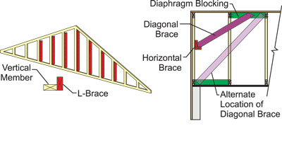
Manufactured gable ends are actually frames even though they are often referred to as trusses. The webs are “studs” oriented vertically and usually spaced at 12, 16 or 24 in. O.C. The gable end frame is designed to transfer vertical loads from the roof to the continuous bearing wall below. Another way gable end frames are different from trusses placed in the interior of the structure is that frames experience perpendicular wind loads. The sheathed frame transfers the wind loads to the roof and ceiling diaphragms and vice versa. The roof and ceiling diaphragms transfer shear loads to the gable end frame, which transfers these loads to the end wall below and into the foundation. In order to do this, the frame relies upon well-designed connections to the bearing wall and diaphragms. If the wind load is high enough and the vertical studs are long enough, the frame may also require a brace to prevent it from rotating the frame and/or buckling the verticals (see Figure 1). This is essentially the same concept as permanent web bracing; therefore, the truss designer is responsible for indicating the location of the bracing for the vertical studs. The building designer is responsible for designing the size and attachment of the brace and how it transfers all the forces into the structure. For gable ends, what is the maximum length a vertical member can be before a lateral brace is required?

Answer:
The maximum length of the vertical member depends on a number of factors. The first factor is the wind force, which in turn depends on the code-defined wind speed, mean roof height, building category and wind exposure due to topographical conditions. Other factors are roof loads, and the size, species and on-center spacing of the vertical studs. Clearly, it is not a straightforward matter.
Luckily most truss designers at truss software companies have simplified matters by producing standard tables and details based on these factors. The best way to find the answer to your specific situation is to call your truss designer to discuss the gable end bracing details for your project. The truss designer may suggest using L-braces along the length of the individual verticals, or horizontal braces that must be stabilized with a diagonal brace that extends into the diaphragms (See Figure 2).
FIGURE 2
These standard tables do some of the work of the building designer with respect to incorporating the gable end frame into the overall structural design, but they do not take the place of a full analysis by the building designer. Other factors the building designer must consider are:
Thickness and type of roof sheathing.
Fastener size, spacing for attaching roof sheathing to the top chord of the gable end frame to resist uplift, lateral wind and diaphragm loads.
Thickness and type of wall sheathing covering the entire gable end wall.
Fastener size and spacing for attaching the gable end wall sheathing.
Attachment of the gable end frame to the supporting wall to resist uplift, shear and lateral wind loads.
Attachment of the gable end wall to the foundation to resist uplift, shear and lateral wind loads.
System for transferring load between wall and gable end frame bottom chord.
In some cases, the expected loads will be too high for the gable end frame, end wall studs or ceiling diaphragm. If so, the building designer might design a balloon-framed end wall, which eliminates the need for a gable end truss. For more information on gable end frame bracing, see the following:
Web Plane & Gable End Frame Bracing
SBCA’s TTB – Gable End Frame Permanent Bracing