Plate Placement
3.7.2 Plate Positioning Procedures
3.7.2.1 Plate Placement
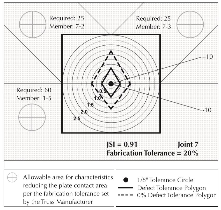
A Joint QC Detail (see Figure 3.7-1), illustrating the positioning tolerance, shall be obtained for any joint selected for inspection, except as permitted in Section 3.7.2.2. The actual midpoint of the Metal Connector Plate shall be within the selected fabrication tolerance polygon as calculated by the Truss Designer for each joint per Section 8.11. However, if the Joint QC Detail contains no polygons and the actual midpoint is within ⅛ in. (3 mm) of the specified midpoint, the placement shall be considered acceptable. If all members of a joint selected for inspection are free from characteristics reducing the plate contact area, consisting of lumber characteristics and flattened teeth as outlined in Section 3.7.4, the 0 percent fabrication tolerance polygon shall be used to evaluate plate positioning. If any member contains characteristics reducing the plate contact area, the 0 percent fabrication tolerance polygon shall be permitted to be used provided that Teeth shall be counted and compared to the minimum required Teeth for that member. If fabrication tolerance polygons are smaller than ½ in. (13 mm) and the actual midpoint falls outside of both polygons but within ½ in. (13 mm) of the specified midpoint, it shall be permitted to evaluate the plate per Section 3.7.2.2. If the actual midpoint does not meet any of these requirements, the procedures set forth in Section 3.9.1 shall be followed.